47-079-01492, part 1
Well drilled in 2008
Producing formation(s): Berea Sandstone, Lower Huron, Rhinestreet, and Marcellus Shales
Geographic location: latitude 38.471964, longitude -81.75069
Visited first in November 2008
Constructing the Site
Constructing the site for drilling a well can be either relatively simple or extremely complex depending on the terrain. Most sites we've examined were cut into the side of a hill. The cut material is pushed over the side of the pad down the fill slope.
The smallest recently drilled pad that we've seen was about 125 feet wide by 300 feet long (measured by pacing so this isn't accurate). We've seen sites that are several times size because of the requirements for construction in hilly terrain or because of the type of well.
The Office of Oil and Gas has created an Erosion and Sediment Control Field Manual for use by operators when constructing sites and roads. The intent is to prevent sediment from polluting the state's waters. When this well was constructed a version of the Manual dating back to the 1990s was being used. A new version of the Manual was released by the Office in 2012.
The actual pad must be level and the drill waste pit should, according to the Manual, be placed on the cut slope, not the fill, side of the pad. The pit is huge, about 10 by 70 by 6 deep feet according to the Manual. The average well produces about 2444 cubic feet of cuttings; that's about the same volume as the main living area in our new house addition.
According to the Argonne National Laboratory's Drill Waste Management web site, pits should have their bottoms no closer than 5 feet from ground water, including seasonally high groundwater. There are no regulations about this in this state. New Mexico won't allow a permanent pit where ground water is closer than 50 feet from the bottom of the pit.
We've only seen one drill site with the rig set up. We'll show photos we took with a critique.
The critique will focus on several points. The site should have sediment control as required in the Manual. The pit should be fenced. And our understanding is that the Manual requires temporary seeding between site construction and reclamation.

Sedimentation control devices include bales of straw, like here, or silt fabric fences.
Bales of straw should be keyed into the ground 4 inches and have two pins holding them in place. Not like here where the bale is wedged into a ditch without keying and with only one pin.

The site is cut into a hillside and this is the cut slope. The slope is too vertical in angle.
No temporary seeding on the site and no ditch to divert runoff to the cut slope from the hillside above.

This is the fill slope below the pad. Runnels cut by water are visible along the top edge. The red/blue material is fencing around the pit which, unlike the Manual's requirements, is on the fill side.
There is a possibility that the weaker fill material will give way, spilling the pit's contents down the hillside.

Below the fill slope are all the cut trees and vegetation from the cleared site, stacked to form a barrier to the mud washing off the pad and down the fill slope.

At one end of the fill slope, between the access road and the cut timber barrier, is a wide ditch. A couple of straw bales are being used as sediment control. They each have a single peg to hold them in place.
If there were a heavy rain, a lot of mud would wash down the hillside past the state road and into the river.

The pit is to the far left along with the mud pump. The red structure is a wheeled office sitting next to the drill rig. Pipe is stacked in the foreground.
Constructing the Road
Most sites we've examined have had fairly short well access roads. Well 47-079-01178 is an exception with a road that is approximately 3/8 mile long.
The Manual has requirements for erosion and sedimentation control along with spacing of culverts and other special structures. A general requirement is for "daylighting" which means clearing the road boundary of trees and vegetation. A width was not given in the Manual but it seems a standard industry practice in this state to daylight from 50 to 60 feet wide, even if the road is single lane. On the West Virginia Surface Owner's Rights Organization website is a photo of a daylighted road through a state park.
The belief is that daylighting will allow sunlight and wind to dry water on the road.
Good road design is constructing a road that sheds water quickly.
We've seen recently constructed roads and older roads, of which both show serious design flaws. These design flaws mean that a road that is daylighted will still have problems with surface moisture.
The best resource we've found for road design is Keller and Sherar, Low-Volume Roads Engineering Best Management Practices Field Guide, and we hope the state adopts it as an adjunct resource to the Manual.
The road that is being constructed will be used immediately by a number of heavy vehicles -- the drill rig, water tankers, dump trucks and so forth. The operator accepts that the road will become trashed and will have to be remade after drilling is finished.
The problem is that the design created during constructing the road is the template that will be used during reclamation. That original, hastily made, design is used to construct a road that will be in use for as long as 75 years (the potential life of a well). We wish a little more thought were put into it.
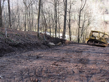
Almost all of our photographs are of reclaimed roads. Here are some of the very short well access road created for a new drill site.

This site is on South Pocatalico River Road about seven miles from where we live. The road is partially graveled between River Road and the pad. This is to help keep mud off the state road.
Above a certain point, the road is unsurfaced. In this case heavy clay forms the roadbed. Two bales of straw are acting as sedimentation control for a ditch on the left side of the road.

On this side of the road the fill slope is in the distance and two large tanks stand on the pad. A wide ditch for runoff is present on the left.

Culverts from the ditches on the other side of the road with bales of straw acting as sedimentation control. The bales are held by one pin, not two, as required. A strong force of water could cause these bales to shift or spin.

A deep ditch on this side of the access road has a bale of straw stuffed in.

Another bale of straw was further down, in the same ditch, closer to the state road. It has acted as a sediment barrier as seen by the built up material on this side of the bale.

A ditch runs in front of the site between a slope and the state road. When we were here, clumps of mud were rolling down the slope into the ditch.
The ditch didn't look adequate for the potential amount of water coming down off the hill.
Visited January 2009
45 Days Later
We revisited the new well site 45 days later. The earlier photographs were taken at the end of November.
There had been heavy rains (but not unusually heavy for the time of year) in December. The existing sediment control structures had been overwhelmed and were no longer being used for primary drainage of the site.
The road and pad had undergone extensive damage. A week after the original photographs were taken we drove by the well site and the drill rig was no longer there. Before reaching the site, we drove for what seemed like a mile or more on an extremely muddy state road. Piles of mud had been scraped off the road and left between the road and the river.
We were told by the man who lives just west of the well site that 30 trucks hauling water and other materials were used in the fracturing of the well and that after a rain the mud washed down the road straight into the river. Because of a complaint of his the operator put in a cross drain (water bar) part way up the road to help reduce some of the water flow.
The cut slope had two slips which are acting to bring trees down to the pad. It looked like the fill slope (where the mud pit was) had slipped also. When we visited on January 12th, all the water on the site was draining past an older well on the flat below, down a bank, into a culvert that passed under the state road and straight into the river. There was no sediment control on the flat, on the bank or at the outlet end of the culvert.
There had never been continuous sediment control between the state road and the river or between the state road and the site, which would have been normally prudent. The cross drain should not have been put in as an afterthought.
The text for Constructing the Site and Constructing the Road had been written before we revisited the site. We were correct in our critique but didn't have the knowledge at that time to judge just how bad things could get.

The gravel on the lower end of the access road has almost completely disappeared. A geotextile blanket should have been used under the gravel.
The gravel should have been replenished when a problem had been first noticed.

This was the sole bale left acting as sediment control for the original ditch. The access road's culvert is to the left.

This bale further up the ditch is the one that had been stuffed into the ditch in the photos taken in November 2008. It was held by only one pin and has spun out of position. Two pins should have been used.
The ditch is noticeably wider now showing the extent of erosion.

The two culverts, about halfway up the access road, almost buried in mud.

The cut slope had slipped in two spots bringing trees down toward the pad.
A ditch and/or berm should have been created above the cut slope to divert water from draining onto the slope. We have yet to note such a feature at the sites we've visited.
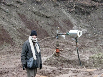
Molly is standing near the new wellhead. The slip has covered a part of the pad.
This is where the drill rig and the red office structure had been on the pad in the earlier photographs.

The pit's fence is completely down and the north side (fill slope side) of the pit is several feet lower than the south side. If the north side gives way, waste from the pit will flow downhill toward the river.

Another view of the pit showing the extent of the fill slope's slipping.

An older well (47-079-00731) is slightly left of center on the lower flat. The water drains from the site just to the right of that well, down a bank, under the road and into the river without sediment control.

The culvert under the access road (the state road is just to the right). The culvert is about 90% blocked with sediment.
The site's drainage system is no longer used here.

This is the well access road which is a straight shot down to the state road where our truck is parked. The river is just on the other side of the state road.
The cross drain is about halfway up the access road.

This photograph was taken at the outlet end of the culvert under the road. Sediment was clearly visible as was a brownish foam.
Another page has photos and text describing our further investigations of this site.
Gas Well Site Visits
Examining Well Sites
How We Examined Well Sites
Environmental Assessment
Table with Links to Wells Visited
47-039-05714 Environmental Assessment
47-079-01492 Environmental Assessment
47-039-02026 Environmental Assessment

Gas Well Study is the examination of natural gas wells in West Virginia.
Underground Injection Control Class 2 Wells
These wells are used either for the disposal of oil and gas liquid waste or for the enhanced recovery of oil or natural gas.
Gas Well Study Site Visits
Annual reports, environmental assessments, and individual well information.
YouTube Videos
Select videos from the Gas Well Study YouTube channel.
What Happened at Fernow
An investigation into what caused the vegetation death in the land application area after landspraying hydraulic fracture flowback waste.
The Spill at Buckeye Creek
An investigation into a spill from a Marcellus well site into Buckeye Creek in Doddridge county.
The Details
Plunger Lift Technology on Gas Wells
Fluids Brought to the Surface during Production
Plugging a Well
How To Read a Lab Report
Information the Completion Report Provides
Casing and Cementing